

") MicroMaster: which inputs need to be high to get motor to move
MicroMaster: which inputs need to be high to get motor to move
Created by: cflex_tech49 at: 2/18/2025 6:33 AM (12 Replies)
Rating  Thanks 1
| 2/18/2025 6:33 AM | |

Joined: 2/10/2025 Last visit: 9/12/2025 Posts: 25 Rating:
|
Hello, my OEM says they are using Digital inputs 1 - 4, based on the parameter could you explain which inputs would need to be high = 1 to get the motor to move and what determines the speed reference? Thank you ------------------------------------------------------------------------------------------ |
Last edited by: Moderator_Lan at: 02/18/2025 07:23:45New subject after splitting |
|
| 2/18/2025 2:35 PM | |


Joined: 3/27/2008 Last visit: 9/14/2025 Posts: 1216 Rating:
|
Digital input. set P051 = 1, on right, DIN1, terminal 5, high to run or set P051 = 2, on left, DIN1, terminal 5, high to run analogue input terminals 3/4, 0/10V, dip switch, 1-on, 2 off, 3 off. 0/20ma, dip switch, 1-off, 2 off, 3 . P006 = 1, analogue control via analogue input signal. Tractor |
|
Tractor |
|

| 2/18/2025 3:19 PM | |
|
Joined: 2/10/2025 Last visit: 9/12/2025 Posts: 25 Rating:
|
I apologize if i was not clear, this is how the parameters are set in the drive and we use inputs 1-4 to operate the motor, however I was unable to determine which inputs need to be turn on in conjunction to work, the electrical drawing has input 1 = start, input 2 = CW , input 3 = CCW, input 4 = HI / LO, so does input 1 plus either input 2 or input 3 for direction and based on status of input 4 it would use this as the speed reference HI / Lo, basically it's set up to use fixed frequencies, |
| 2/19/2025 2:24 PM | ||
|
Joined: 3/27/2008 Last visit: 9/14/2025 Posts: 1216 Rating:
|
You said:
Reply: Input 1, start, as the inputs 2 and 3 give the 'run' command, 'start' does not apply to this drive, the power is applied and the drive is ready to run, either CW or ACW, depending upon the closure to input 2 or input 3 of a HI signal. Input 2, set P052 = 1, the motor will run ' ON RIGHT'. Input 3, set P053 = 2, the motor will run 'ON LEFT'. Input 4, set P054 = 13, the 'setpoint' can be switched between analogue and fixed frequency control. I hope this answers the question, I have attached a scan of the digital input page. I do not have a drive of this type so cannot test these things other than looking at a very old manual. Come back if I can help further. Tractor AttachmentDocument_2025-02-19_140831.pdf (372 Downloads) |
|
Last edited by: Tractor at: 02/19/2025 14:25:27Last edited by: Tractor at: 02/19/2025 14:27:02Tractor |
||
| 2/20/2025 2:58 PM | |
|
Joined: 3/27/2008 Last visit: 9/14/2025 Posts: 1216 Rating:
|
Having difficulty seeing how this can work with Micromaster Vector. From the drawing, Din2, Din3, or Din4, are being activated when Din1 is selected high. I cannot see a way of replicating this with Micromaster Vector. As I have shown, each Digital Input Din2/3/4, when high make the selection required when high, making Din1 surplus? I believe some manufacturers operate as shown in your drawing, Danfoss and ABB perhaps? Thanks for the reply and 'follow up'. Tractor |
|
Tractor |
|
| 2/20/2025 6:06 PM | |
|
Joined: 2/10/2025 Last visit: 9/12/2025 Posts: 25 Rating:
|
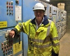
it connected to a plc, which certain outputs come on that make certain inputs high, this is exactly how it is hooked up in our plant, i sent the picture of the drive in an earlier post, you may be able to make out the wire numbers and terminals, based on how our drive is wired, and the parameters i sent in the earlier post of fixed frequencies, so if only input 2 is made high parameter P52 = 1 H = ON right, would anything happen, I should probably try to look in the plc program and see which outputs are sent to the drive for rotate right high speed, rotate right low speed, and the same with rotate left, Thank you for all your time and help |
| 2/21/2025 2:41 PM | |
|
Joined: 3/27/2008 Last visit: 9/14/2025 Posts: 1216 Rating:
|
Hi I can see the following are possible, I am assuming the setting's are as below, possible, as I do not have sight of actual parameter settings: Input 2, set P052 = 1, the motor will run ' ON RIGHT', (Din6, 1202). Input 3, set P053 = 2, the motor will run 'ON LEFT', (Din7, 1203). Input 4, set P054 = 13, (Din8, 1204), the 'setpoint' can be switched between analogue and fixed frequency control. Now: K3505 is a contact connected to Din1, 1201 / 6516, without a parameter setting for this, I cannot be sure what it does, I doubt it is a 'START' command. I suggest it is connected, and see what happens when it goes high. Or send me the parameter setting for P051? Do you have the manuals available for this drive? Tractor
|
|
Tractor |
|
This contribution was helpful to
|
|
| 2/22/2025 9:12 AM | |
|
Joined: 2/10/2025 Last visit: 9/12/2025 Posts: 25 Rating:
|
here are the parameter settings |
| 2/23/2025 12:49 PM | |
|
Joined: 3/27/2008 Last visit: 9/14/2025 Posts: 1216 Rating:
|
From the settings: P042 = FF2 set to 55Hz. 1201, Din1, P051 = 6, select fixed frequency, 'this may be a START command'. 1202, Din2, P052 = 1, on right. 1203, Din3, P053 = 2, on left. 1204, Din4, P054 = 6, fixed frequency set to 55Hz. Notes: Closing Din1 may be the START, unable to confirm this without having a device here to evaluate. Frequency setpoint source, P006 = 2, this should be selected. Tractor |
|
Tractor |
|
| 2/23/2025 3:44 PM | |
|
Joined: 2/10/2025 Last visit: 9/12/2025 Posts: 25 Rating:
|
looks like P006 = 2 |
| 2/23/2025 3:51 PM | |
|
Joined: 2/10/2025 Last visit: 9/12/2025 Posts: 25 Rating:
|
Attachmentfull parameter set mmv.pdf (234 Downloads) |
| 2/23/2025 4:02 PM | |
|
Joined: 2/10/2025 Last visit: 9/12/2025 Posts: 25 Rating:
|
|
Follow us on