Industry Online Support
Technical Forum


| 7/7/2018 7:51 AM | |


Joined: 4/28/2017 Last visit: 3/14/2024 Posts: 149 Rating:
|
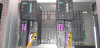
Dear Expert, We are having 90 slaves in a Profibus network. Controlled by 443-5 EXT CP card as master. And, my AS is Simatic 417-4 CPU. Initially, I added all the slaves in the Profibus network with unique slave IDs. The local configuration also has been done in the right manner at the field. When I monitor the connected device in Hardware configuration online, initially all were absent. Then, we connected only one field device in the network. It was detected. All these slaves are in IMCC feeders. Respectively TesysT (Schneider) and Danfoss Drive. So, when we connect all the devices from the first feeder it was connected. But, if we connect the second feeder devices a couple of device from the first feeder gone offline. Then, if we connect next to 15 th slaves, the entire slave is gone offline. What will be the problem ???, we verified the Wiring connections, Continuity. It’s okay. Then, All the slave is wired using 485 (2-wire) terminal connectors. It’s not the Siemens Profibus connector. Then, My CPU won’t go to stop mode since we have respective OB call in the program. Also, CPU property assignment. And, when I monitor the CP card Diagnostics, I was able to see some slaves IDs which was not connected in Online. How do I can bring all these slaves online??? Kindly provide your suggestions. I will be thankful. Here are some photos in detail. Attachment23.zip (312 Downloads) |
|
Note: If this post did really help you, you may use the "Rate" button to express your support, Thank you. |
|
| 7/9/2018 3:24 PM | |

Joined: 9/27/2006 Last visit: 9/21/2024 Posts: 12282 Rating:
|
Hello Sanakyen; I have checked the forum today and did not find the extra documents you were to provide, so here are some partial answers to your questions, with the information I have. Use the attachment for sources, the different images are not necessarily in the order of your questions. - Point ii: Look at attachment picture no 3: with a single cable you should connect to terminal A1-B1 of the connector, and set the termination to ON. This image and other relevant information can be seen in the following manual for Profibus Networks; it dates from 2001 but the information is still very useful: https://support.industry.siemens.com/cs/at/en/view/1971286 - Point iii: Refer to picture no 1. The Red cable corresponds to the Positive (P) connection, the Green cable is the (N) connection. As stated in image 4, please check that all connections repect the continuous color coding, with Profibus connectors and with terminals; it requires a coninuity check between all Profibus connections, which may take time but will remove any doubt. - Point iv: Whenever you use a repeater, it is to isolate/retransmit on 2 Profibus segments. Each segment must be terminated at each end, which means you have to learn to setup the termination switches on the repeater correctly. In the case you describe, A1-B1 (segment S1) to A2-B2 (segment S2), both termination switches S1 and S2 must be ON; see the attachment, image 2, and the termination of the end-point of the segment must also be ON (so the segment is correctly terminated at both ends). Examine image 2 in the attachment. The Mode switch (inset between the switches S1 and s2 on the repeater) disconnects segments S1 and s2; it must be OFF if you want both segments to communicate. - Point v: all Profibus slaves should take their bus speed reference from the master, unless the master determines that one or more of the slaves are not able to follow at the automatic speed (Profibus-PA slaves, for example). Then the master will set the speed for all slaves at the lower boundary limited by this slave's GSD file. Hope this helps, Daniel Chartier |
Last edited by: dchartier at: 7/9/2018 3:31:52 PMLast edited by: dchartier at: 7/9/2018 3:34:50 PM |
|
This contribution was helpful to
|
|
| 7/11/2018 7:29 AM | |
|
Joined: 4/28/2017 Last visit: 3/14/2024 Posts: 149 Rating:
|
Dear Daniel Chartier, Thank you for your detailed response, Actually, Sorry I couldn't add some documents since I was engaged. Then, Whatever you have described in the Point number II, III, IV is the truth. As initially, I followed that way. but, there was no response from the field. Then, Just I tried some other way. In the end, I wondered there was a couple of slaves detected. So, Finally, I have made the changes as what you have described. Now, We connected one more Siemens Repeater just after the first 15 nodes. And, I have attached some image copies. Consist of i) Slave Wiring detail, (For Danfoss Drive and Tesys T Motor controller) ii) Profibus connector connection, iii) CP card Diagnostic Report, iv) Configured Profibus Network Speed. v) Hand sketch Outline diagram of the Profibus network. Kindly have a look at it. Now, The first 15 slaves are detected. But, the rest of them not responding. Also, I looked at the CP card Diagnostic. The Profibus speed was changed into lower boundary limit as what you informed in the point no V. So, Kindly suggest me what speed should I configure now. How do I can go forward? AttachmentIMCC_PF_Detail_to_Sie_Forum.zip (278 Downloads) |
Last edited by: Sanakiyen at: 7/11/2018 7:30:24 AMNote: If this post did really help you, you may use the "Rate" button to express your support, Thank you. |
|


Follow us on